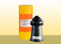
PIPELIFE GAS-STOP™. Excess flow valves for polyethylene gas service lines and networks.
| Excess flow valve Gas-Stop YELLOW serie 1 ÷ 5 bar |
||
| Item | Diameter | Flow rate m3h |
| GS 20/1* | 20 | 25 |
| GS 20/1UE | 20 | 25 |
| GS 32/1* | 32 | 100 |
| GS 32/1UE | 32 | 100 |
| GSA 20/1* | 20 | 25 |
| GSA 20/1UE | 20 | 25 |
| GSA 32/1* | 32 | 100 |
| GSA 32/1UE | 32 | 100 |
| Excess flwo valve Gas-Stop RED serie 0,2 ÷ 5 bar |
||
| Item | Diameter | Flow rate m3h |
| GS 32/200 | 32 | 36 ÷ 80 |
| GS 32/200UE | 32 | 36 ÷ 80 |
| GS 50/200 | 50 | 110 ÷ 240 |
| GS 50/200UE | 50 | 110 ÷ 240 |
| GS 63/200 | 63 | 180 ÷ 400 |
| GS 63/200UE | 63 | 180 ÷ 400 |
| GS 110/200 | 110 | 460 ÷ 1180 |
| GS 110/200UE | 110 | 460 ÷ 1180 |
| GSA 32/200* | 32 | 36 ÷ 80 |
| GSA 32/200UE | 32 | 36 ÷ 80 |
| GSA 50/200 | 50 | 110 ÷ 240 |
| GSA 50/200UE | 50 | 110 ÷ 240 |
| GSA 63/200 | 63 | 180 ÷ 400 |
| GSA 63/200UE | 63 | 180 ÷ 400 |
| GSA 110/200 | 110 | 460 ÷ 1180 |
| GSA 110/200UE | 110 | 460 ÷ 1180 |
| GSA 110/150UE | 110 | 410 ÷ 1020 |
Remark: For GSA 110/150 minimum working pressure 150 mbar.
|
Excess flow valve |
||
| Item | Diameter | Flow rate m3h |
| GS 63/300UE | 63 | 200 ÷ 590 |
| GS 63/300UES | 63 | 255 ÷ 750 |
| GSA 63/300UE | 63 | 200 ÷ 590 |
| GSA 63/300UE | 63 | 255 ÷ 750 |
| GSA 110/300UE | 110 | 540 ÷ 1750 |
| GSA 110/300UES | 110 | 650 ÷ 2140 |
| Excess flow valve Gas-Stop GREEN serie 0,015 ÷ 1 bar |
||
| Item | Diameter | Flow rate m3h |
| GS 50/15UE | 50 | 16 |
| GS 63/15UE | 63 | 25 |
| GSA 50/15UE | 50 | 16 |
| GSA 63/15UE | 63 | 25 |
| Excess flow rate Gas-Stop BLUE serie 0,025(0,030) ÷ 1 bar |
||
| Item | Diameter | Flow rate m3h |
| GS 32/25UE | 32 | 10 ÷ 14 |
| GS 50/25UE | 50 | 25 ÷ 36 |
| GS 63/25UE | 63 | 40 ÷ 55 |
| GSA 32/25UE | 32 | 10 ÷ 14 |
| GSA 50/25UE | 50 | 25 ÷ 36 |
| GSA 63/25UE | 63 | 40 ÷ 55 |
| GS 110/30UE | 110 | 120 ÷ 165 |
| GSA 110/30UE | 110 | 120 ÷ 165 |
Remark :GS e GSA 110/300 minimum working pressure 30 mbar
General remarks
UE=With overflow mechanism
UES=With overflow mechanism and increased flow rate
-Flow rate refer to air under normal conditions (1013,25 mbar,15°C)

GS/GSA 63

GS-GSA 110


